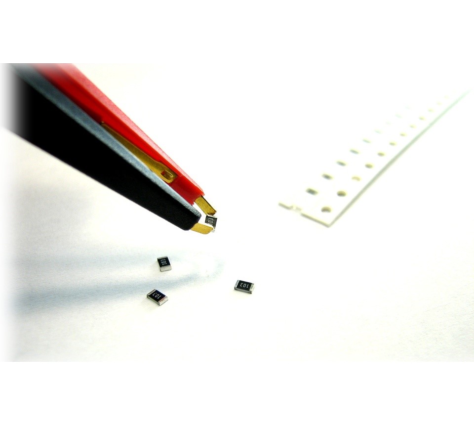
The Atlas LCR40 automatically identifies and analyses almost any passive component (Inductor, Capacitor or Resistor). It measures its parameters using automatically selected test frequencies (DC, 1kHz, 15kHz and 200kHz).
Inductance from 1uH to 2H (min resolution is 0.8uH), Capacitance from 1pF to 10000uF (min resolution is 0.5pF) and Resistance from 1ohm to 2Mohm.
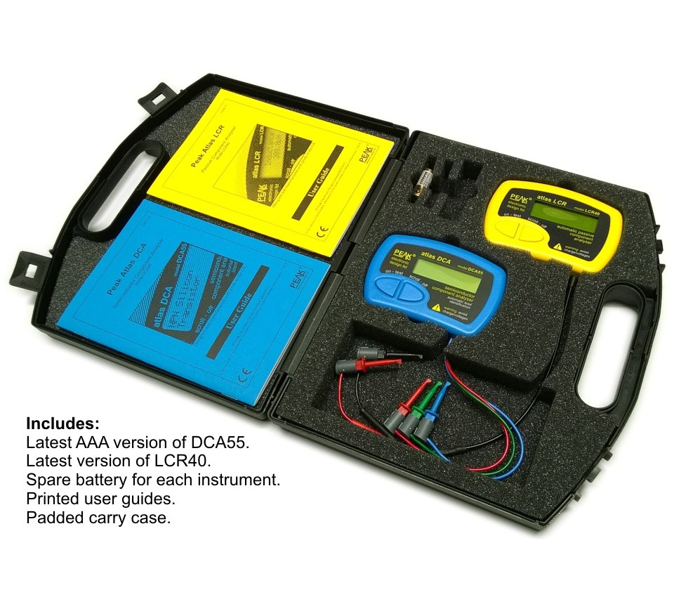
Includes:- LCR40 Passive Component Analyser.
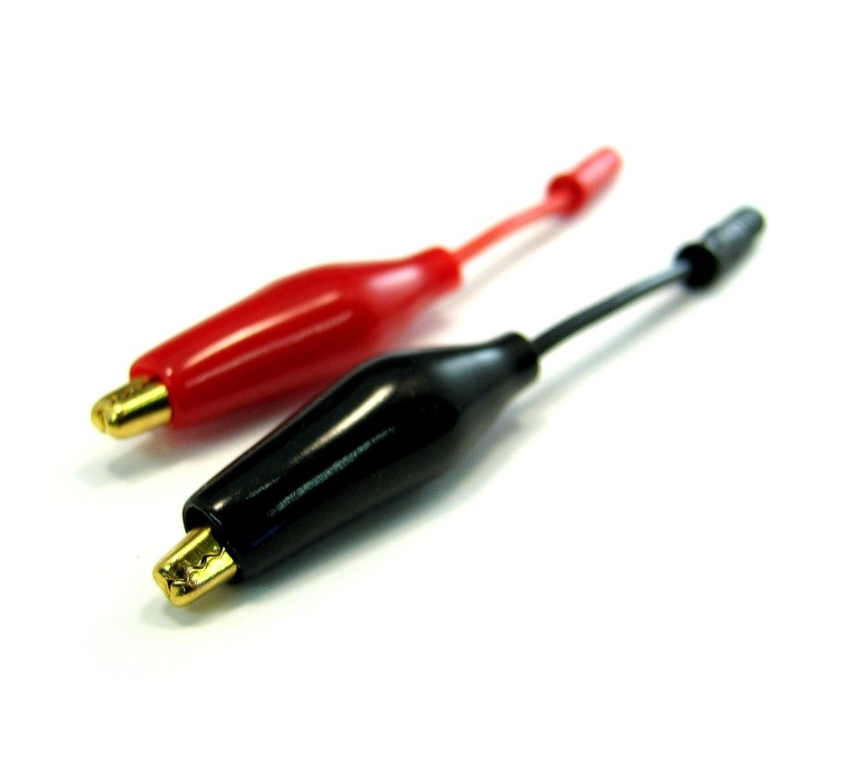
- 2mm plugs and sockets and removeable hook probes.
- Comprehensive illustrated user guide.
- 2 Batteries, one installed and one spare. GP23 Alkaline battery. (12V 55mAH).
Technical Specifications
Resistance: 1 Ohm to 2 MegOhms, resolution typically 0.6 Ohms, accuracy typically ±1.0% ±1.2 Ohms
Inductance: 1uH to 2H, resolution typically 0.8uH, accuracy typically ±1.5% ±1.6uH
Capacitance: 0.5pF to 10000uF, resolution typical 0.5pF, accuracy typically ±1.5% ±1.0pF
Open circuit test voltage: ±1.05V
Short circuit test current: ±3.25mA
Test frequencies: DC, 1kHz, 14.925kHz and 200kHz, ±1.5%
Sine purity: -60dB 3rd harmonic typical
Operating temperature range: 15°C to 35°C (60°F to 95°F)
Battery type: GP23A or V23A or MN21 (12V 55mAH type)
Battery life: Typically ~1600 operations at <1 minute per operation
Display type: Alphanumeric LCD (low level backlight)
Please avoid charge/voltage on the probes.Accuracies shown for 100uH-100mH, 200pF-500nF and 10 Ohms to 1MOhms.
FAQs
Q. Can I use this in-circuit?
A. No, it is not recommended for in-circuit use. Other component interactions can cause misleading results and damage may result from unexpected charged devices.
Q. Is the LCR40 protected against charge on the probes?
A. The LCR40 is protected against small charges on the probes (<5V on 22000uF, <25V on 10uF). Like all LCR meters, it is vital that you avoid charges on the probes.
Q. Is the LCR45 better than the LCR40 for low inductances?
A. Yes. The use of a finer resolution ADC provides significantly finer measurements when measuring below 1µH.
Q. Is the LCR40 calibrated?
A. Yes. Every LCR40 is individually calibrated to standards that are traceable to international standards.
Q. Why does the calibration certificate cost extra if all LCR40s are calibrated anyway?
A. The calibration certificate includes the results of a manual calibration verification process with results from 25 known standard values.
Q. Why does the display shows a "Calibration due" date of xx/xxxx?
A. The "Calibration Due Date" is purely a recommendation. Nothing bad happens after that date. New LCR instruments will have a date shown that is approximately 12-18 months in the future. The generally accepted recalibration interval for this type of instrument is 12 months. The LCR40/45 can only be re-calibrated here at Peak which uses a very comprehensive 24 station rig, the calibration-due date is then set to 12 months from that moment. It is not mandatory to have a re-calibration.
Q. Why does the measured value appear to be incorrect.
A. Ensure probes are well connected to the component under test for the entire duration of the analysis.
A. Ensure that nothing else is connected with the component under test. Make sure you are not touching the connections.
A. The component value may be outside the supported measurement range.
A. The component's design frequency may not correspond to the test frequencies used by the Atlas LCR.
Q. Why do measured values vary slightly between tests.
A. The displayed resolution is finer than the internal measurement resolution to avoid rounding errors. Small variations within the quoted measurement resolutions are normal.
Q. The display shows a "Calibration due" date of xx/xxxx.
A. The "Calibration Due Date" is purely a recommendation. Nothing bad happens after that date. New LCR instruments will have a date shown that is approximately 12-18 months in the future. The generally accepted recalibration interval for this type of instrument is 12 months. The LCR40/45 can only be re-calibrated here at Peak which uses a very comprehensive 24 station rig, the calibration-due date is then set to 12 months from that moment. It is not mandatory to have a re-calibration.
Q. Why does the display shows "Low Resistance and Inductance" when testing some components?
A. It will still provide measurements. This message is displayed when the LCR40 is measuring a low resistance and low inductance component and cannot be certain whether it is an inductor or a resistor (as they can have very similar properties at low values). Simply press the scroll button on the unit and you will see the measurements for both inductance and resistance.
Downloads
Data Sheet (EN)User Guide (EN)User Guide (DE)User Guide (IT)User Guide (FR)Optional certificate of calibration includes results of manual verification tests. Instrument is calibrated the same way regardless of whether you require the certificate.
Please note that the product colour/appearance may vary.
Current firmware: 3.80