| ATPK2 Reseller Resources | |||||||||||||||||||||||||||||||||||||||||||||||||||||||||||||||||||||||||||||||||||||||||||||||||||||||||||||||||||||||||||||||||||||||||||||||||||||||||||||||||||||||||||||||||||||||||||||||||||||||||||||||||||||||||||||||||||||||||||||||||||||||||||||||||||||||||||||||
| Updated 15/03/2025 | |||||||||||||||||||||||||||||||||||||||||||||||||||||||||||||||||||||||||||||||||||||||||||||||||||||||||||||||||||||||||||||||||||||||||||||||||||||||||||||||||||||||||||||||||||||||||||||||||||||||||||||||||||||||||||||||||||||||||||||||||||||||||||||||||||||||||||||||
| Title | Atlas Star Pack - Semiconductor and Passive Component Analyser Pack (Models DCA55 and LCR40) | ||||||||||||||||||||||||||||||||||||||||||||||||||||||||||||||||||||||||||||||||||||||||||||||||||||||||||||||||||||||||||||||||||||||||||||||||||||||||||||||||||||||||||||||||||||||||||||||||||||||||||||||||||||||||||||||||||||||||||||||||||||||||||||||||||||||||||||||
| UPC | 850061273093 | ||||||||||||||||||||||||||||||||||||||||||||||||||||||||||||||||||||||||||||||||||||||||||||||||||||||||||||||||||||||||||||||||||||||||||||||||||||||||||||||||||||||||||||||||||||||||||||||||||||||||||||||||||||||||||||||||||||||||||||||||||||||||||||||||||||||||||||||
| Catalogue copy | A fantastic dual
instrument pack featuring the Atlas DCA Semiconductor Analyser and the
Atlas LCR Passive Component Analyser. Housed in a robust padded case,
complete with spare battery, user guide and space for accessories.
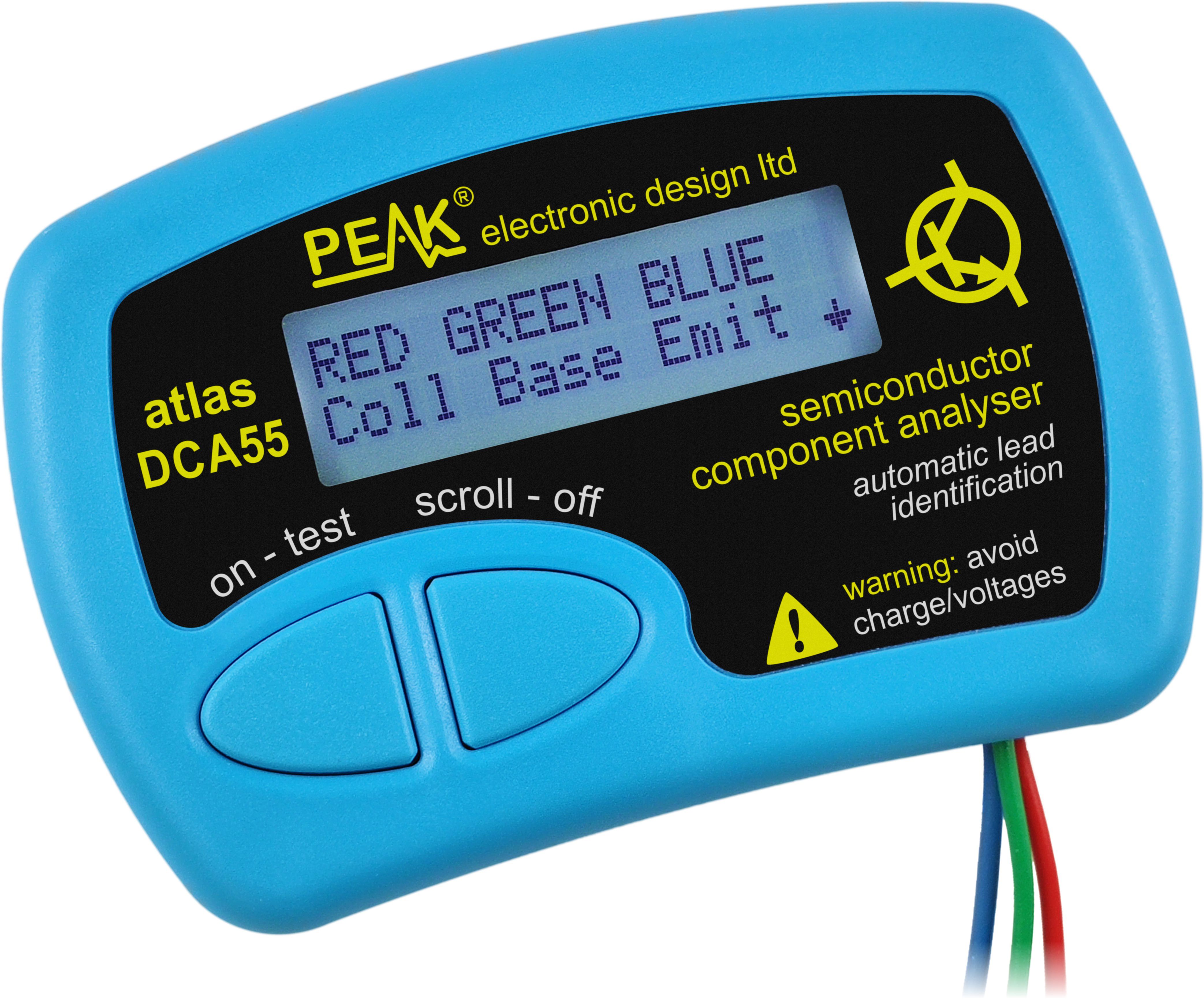
DCA55: Connect any way round to automatically identify and measure a wide range of semiconductor devices. The DCA55 will automatically identify the type of the part, pinout and many component parameters. Components supported include bipolar NPN/PNP transistors, darlingtons, diode-protected transistors, transistors with built-in resistors, enhancement mode MOSFETs, depletion mode MOSFETs, diodes, diode networks, LEDs, 2 and 3 lead bicolour LEDs, JFETs and many more. Further measurements are displayed including transistor gain, leakage current, pn voltage drops, LED voltages, MOSFET threshold voltages and much more. Even if you don't know anything about the part, just connect it in any configuration and the DCA55 will identify the type of part for you and also identify all the leads. Supplied with universal gold plated hook probes, battery and illustrated user guide. Not designed for in-circuit testing. Key Features:
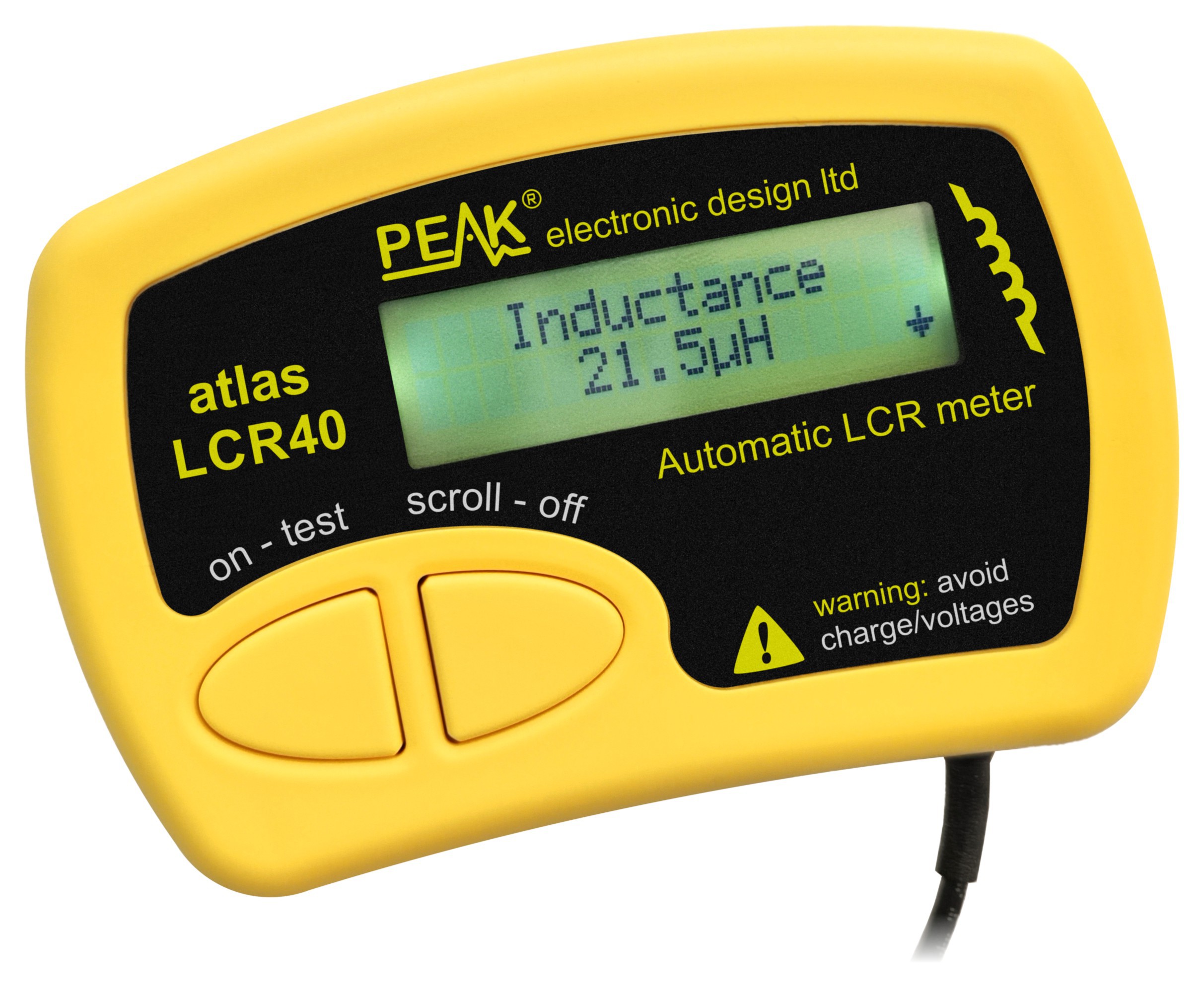
Handheld LCR analyser providing measurements for inductance, capacitance and resistance. The component type is automatically detected for you, just connect and press "test". The test frequency is automatically selected to provide the best measurement resolution. Test frequencies include DC, 1kHz, 15kHz and 200kHz. Inductance from 1uH to 2H, minimum resolution of 1uH, typical accuracy of ±1.5% between 100uH and 100mH. Capacitance from 1pF to 10,000uF, minimum resolution of 1pF typical accuracy of ±1.5% between 200pF and 500nF. Resistance from 1R to 2MR, typical accuracy of ±1%. Test frequency is displayed with the measurement. Inductor DC resistance also displayed when testing inductors. Supplied with removable gold plated hook probes, battery and user guide. Compatible with standard 2mm test connectors. Not designed for in-circuit use. Key Features
|
||||||||||||||||||||||||||||||||||||||||||||||||||||||||||||||||||||||||||||||||||||||||||||||||||||||||||||||||||||||||||||||||||||||||||||||||||||||||||||||||||||||||||||||||||||||||||||||||||||||||||||||||||||||||||||||||||||||||||||||||||||||||||||||||||||||||||||||
| Specification Summary at 20°C (68°F) unless otherwise specified. | DCA55:
|
||||||||||||||||||||||||||||||||||||||||||||||||||||||||||||||||||||||||||||||||||||||||||||||||||||||||||||||||||||||||||||||||||||||||||||||||||||||||||||||||||||||||||||||||||||||||||||||||||||||||||||||||||||||||||||||||||||||||||||||||||||||||||||||||||||||||||||||
| Photography (click to enlarge) | 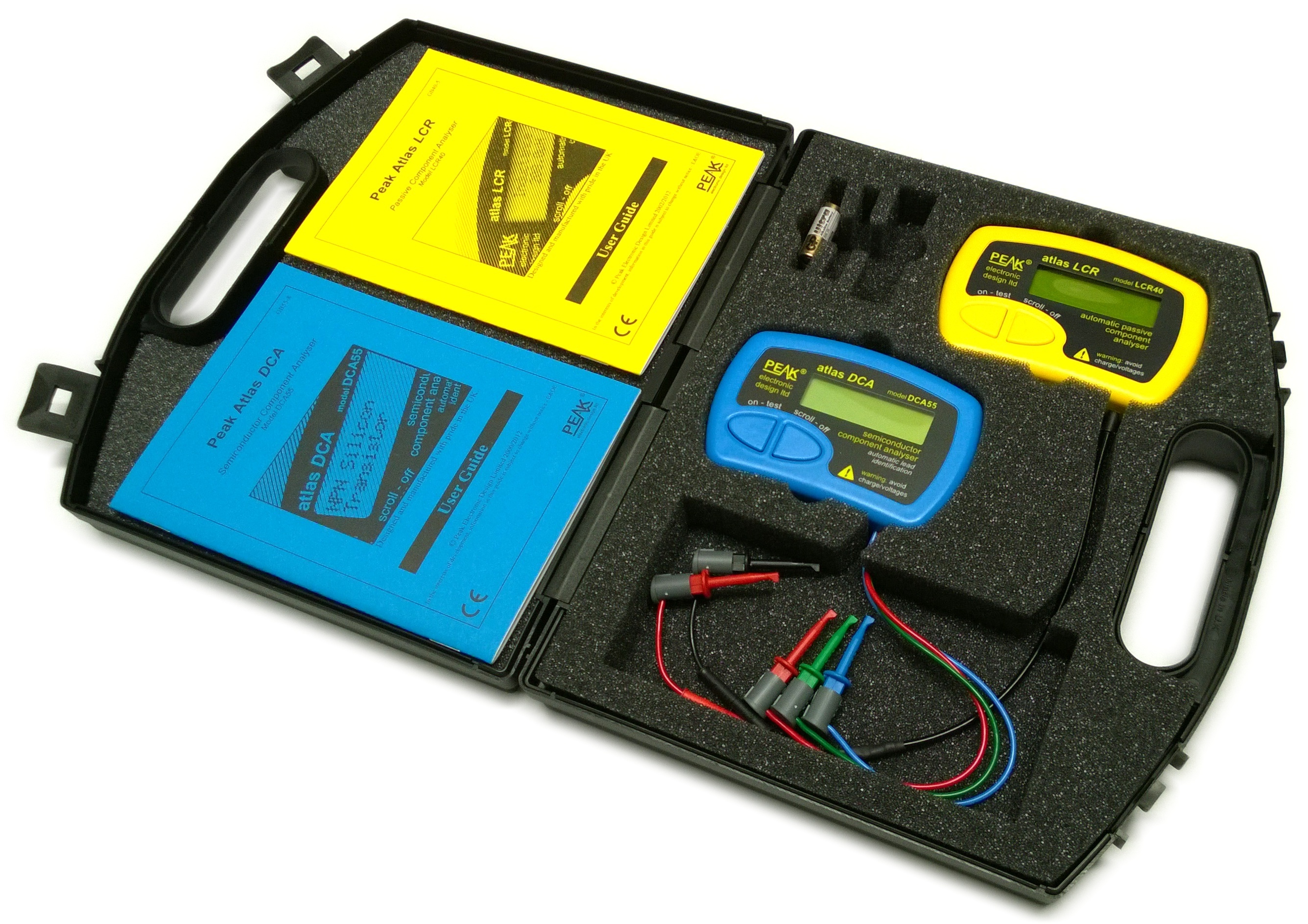 |
 |
 |
 |
|||||||||||||||||||||||||||||||||||||||||||||||||||||||||||||||||||||||||||||||||||||||||||||||||||||||||||||||||||||||||||||||||||||||||||||||||||||||||||||||||||||||||||||||||||||||||||||||||||||||||||||||||||||||||||||||||||||||||||||||||||||||||||||||||||||||||||
|
|
|||||||||||||||||||||||||||||||||||||||||||||||||||||||||||||||||||||||||||||||||||||||||||||||||||||||||||||||||||||||||||||||||||||||||||||||||||||||||||||||||||||||||||||||||||||||||||||||||||||||||||||||||||||||||||||||||||||||||||||||||||||||||||||||||||||||||||||||
| Other Downloads | lcr40-user-guide-en.pdf | dca55-user-guide-en.pdf | |||||||||||||||||||||||||||||||||||||||||||||||||||||||||||||||||||||||||||||||||||||||||||||||||||||||||||||||||||||||||||||||||||||||||||||||||||||||||||||||||||||||||||||||||||||||||||||||||||||||||||||||||||||||||||||||||||||||||||||||||||||||||||||||||||||||||||||
| lcr40-user-guide-de.pdf | dca55-user-guide-de.pdf | ||||||||||||||||||||||||||||||||||||||||||||||||||||||||||||||||||||||||||||||||||||||||||||||||||||||||||||||||||||||||||||||||||||||||||||||||||||||||||||||||||||||||||||||||||||||||||||||||||||||||||||||||||||||||||||||||||||||||||||||||||||||||||||||||||||||||||||||
| lcr40-user-guide-it.pdf | dca55-user-guide-it.pdf | ||||||||||||||||||||||||||||||||||||||||||||||||||||||||||||||||||||||||||||||||||||||||||||||||||||||||||||||||||||||||||||||||||||||||||||||||||||||||||||||||||||||||||||||||||||||||||||||||||||||||||||||||||||||||||||||||||||||||||||||||||||||||||||||||||||||||||||||
| lcr40-user-guide-fr.pdf | dca55-user-guide-fr.pdf | ||||||||||||||||||||||||||||||||||||||||||||||||||||||||||||||||||||||||||||||||||||||||||||||||||||||||||||||||||||||||||||||||||||||||||||||||||||||||||||||||||||||||||||||||||||||||||||||||||||||||||||||||||||||||||||||||||||||||||||||||||||||||||||||||||||||||||||||
| lcr40_datasheet_en.pdf | dca55_datasheet_en.pdf | ||||||||||||||||||||||||||||||||||||||||||||||||||||||||||||||||||||||||||||||||||||||||||||||||||||||||||||||||||||||||||||||||||||||||||||||||||||||||||||||||||||||||||||||||||||||||||||||||||||||||||||||||||||||||||||||||||||||||||||||||||||||||||||||||||||||||||||||
| Dimensions per product (excluding leads) | 103 x 70 x 20 mm (4.1" x 2.8" x 0.8") | ||||||||||||||||||||||||||||||||||||||||||||||||||||||||||||||||||||||||||||||||||||||||||||||||||||||||||||||||||||||||||||||||||||||||||||||||||||||||||||||||||||||||||||||||||||||||||||||||||||||||||||||||||||||||||||||||||||||||||||||||||||||||||||||||||||||||||||||
| Dimensions per product (packaged) | 268 x 225 x 55 mm (10.5" x 8.9" x 2.2") | ||||||||||||||||||||||||||||||||||||||||||||||||||||||||||||||||||||||||||||||||||||||||||||||||||||||||||||||||||||||||||||||||||||||||||||||||||||||||||||||||||||||||||||||||||||||||||||||||||||||||||||||||||||||||||||||||||||||||||||||||||||||||||||||||||||||||||||||
| Weight per product (nett) | 0.671kg (1lb 8oz) | ||||||||||||||||||||||||||||||||||||||||||||||||||||||||||||||||||||||||||||||||||||||||||||||||||||||||||||||||||||||||||||||||||||||||||||||||||||||||||||||||||||||||||||||||||||||||||||||||||||||||||||||||||||||||||||||||||||||||||||||||||||||||||||||||||||||||||||||
| Weight per product (packaged inc docs) | 0.758kg (1lb 11oz) | ||||||||||||||||||||||||||||||||||||||||||||||||||||||||||||||||||||||||||||||||||||||||||||||||||||||||||||||||||||||||||||||||||||||||||||||||||||||||||||||||||||||||||||||||||||||||||||||||||||||||||||||||||||||||||||||||||||||||||||||||||||||||||||||||||||||||||||||
| Bulk order multiple | 20, 80 | ||||||||||||||||||||||||||||||||||||||||||||||||||||||||||||||||||||||||||||||||||||||||||||||||||||||||||||||||||||||||||||||||||||||||||||||||||||||||||||||||||||||||||||||||||||||||||||||||||||||||||||||||||||||||||||||||||||||||||||||||||||||||||||||||||||||||||||||
| Harmonisation / Commodity / Tariff Code | 9030 8200 GB | ||||||||||||||||||||||||||||||||||||||||||||||||||||||||||||||||||||||||||||||||||||||||||||||||||||||||||||||||||||||||||||||||||||||||||||||||||||||||||||||||||||||||||||||||||||||||||||||||||||||||||||||||||||||||||||||||||||||||||||||||||||||||||||||||||||||||||||||
| Fundamental Materials | Plastic, glass and metal. | ||||||||||||||||||||||||||||||||||||||||||||||||||||||||||||||||||||||||||||||||||||||||||||||||||||||||||||||||||||||||||||||||||||||||||||||||||||||||||||||||||||||||||||||||||||||||||||||||||||||||||||||||||||||||||||||||||||||||||||||||||||||||||||||||||||||||||||||
| Country of manufacture | England (UK) | ||||||||||||||||||||||||||||||||||||||||||||||||||||||||||||||||||||||||||||||||||||||||||||||||||||||||||||||||||||||||||||||||||||||||||||||||||||||||||||||||||||||||||||||||||||||||||||||||||||||||||||||||||||||||||||||||||||||||||||||||||||||||||||||||||||||||||||||
| Certification | CE, WEEE, ROHS | ||||||||||||||||||||||||||||||||||||||||||||||||||||||||||||||||||||||||||||||||||||||||||||||||||||||||||||||||||||||||||||||||||||||||||||||||||||||||||||||||||||||||||||||||||||||||||||||||||||||||||||||||||||||||||||||||||||||||||||||||||||||||||||||||||||||||||||||
| Keywords | peakelec, peak electronic design, peak electronics, peak electronic, Peak Atlas, Atlas, DCA55, DCA50, DCA50e, Atlas DCA, DCA, Semiconductor tester, semiconductor analyser, semiconductor analyzer, transistor tester, transistor analyser, transistor analyzer, component tester, component analyser, component analyzer, component identifier, semiconductor identifier, LCR40, Atlas LCR, LCR, LCR Bridge, LC Bridge, LC Meter, Passive component tester, Passive component analyser, Passive component analyzer, Passive component meter, inductor meter, inductance meter, inductor tester, capacitor meter, capacitance meter, capacitor tester, resistor meter, resistance meter, resistor tester, Atlas Pack, Atlas Star Pack, Atlas Hobby Pack, ATPK2. | ||||||||||||||||||||||||||||||||||||||||||||||||||||||||||||||||||||||||||||||||||||||||||||||||||||||||||||||||||||||||||||||||||||||||||||||||||||||||||||||||||||||||||||||||||||||||||||||||||||||||||||||||||||||||||||||||||||||||||||||||||||||||||||||||||||||||||||||
| Related products | UPS56, GP23A, SMD03M, CRC01M, PTPM, LCRLHP2, PCA23 | ||||||||||||||||||||||||||||||||||||||||||||||||||||||||||||||||||||||||||||||||||||||||||||||||||||||||||||||||||||||||||||||||||||||||||||||||||||||||||||||||||||||||||||||||||||||||||||||||||||||||||||||||||||||||||||||||||||||||||||||||||||||||||||||||||||||||||||||